Flannel CNI under the hood

In this article, we will do a deep dive into how the flannel cni networking works.
Introduction
Flannel is layer 3 overlay network fabric for Kubernetes, which is very simple to install and easy to administer. By default, Flannel is configured to use the 10.244.0.0/16 CIDR block and vxlan as the backend mechanism, as defined in the kube-flannel.yaml
  net-conf.json: |
    {
      "Network": "10.244.0.0/16",
      "Backend": {
        "Type": "vxlan"
      }
    }
Flanneld runs inside kube-flannel-ds-* pod (daemon set) on each node and shares the same network namespace as the host node. Due to this reason its able to configure the host networking for vxlan tunnels.
% k get pods -n kube-flannel -o wide
NAME                    READY   STATUS    RESTARTS        AGE   IP           NODE                           NOMINATED NODE   READINESS GATES
kube-flannel-ds-6ql4k   1/1     Running   6 (2d15h ago)   45d   172.20.0.2   flannelcluster-control-plane   <none>           <none>
kube-flannel-ds-9cnkx   1/1     Running   7 (2d15h ago)   45d   172.20.0.3   flannelcluster-worker2         <none>           <none>
kube-flannel-ds-lmcs4   1/1     Running   7 (2d15h ago)   45d   172.20.0.4   flannelcluster-worker          <none>           <none>
2 High level overview
A high level overview of how the flannel networking works is as shown below. (credits)
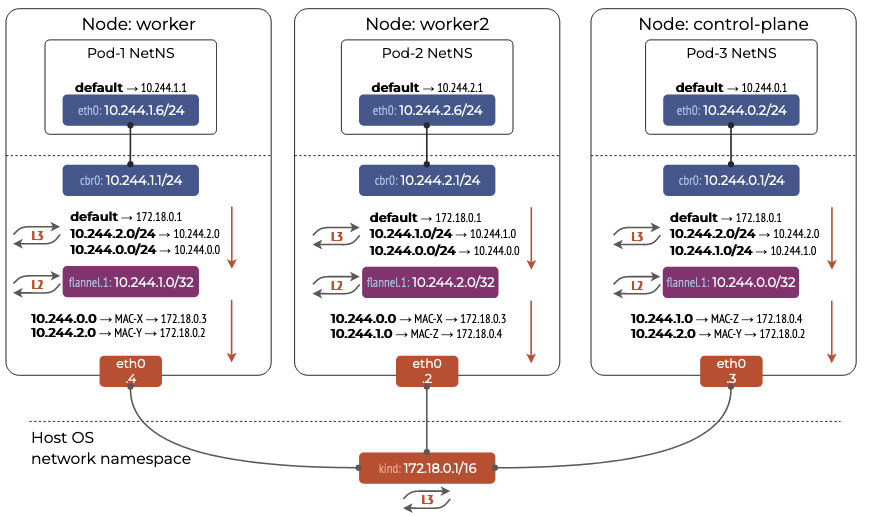
Looking at the picture, we see that, Flannel has created a 10.244.0.0/16 network and has allocated each node in the cluster a 10.244.X.0/24 CIDR block. This means 254 pods can be connected on each node to the flannel network. The details of the subnet lease can be obtained from:
root@flannelcluster-worker:/# cat /run/flannel/subnet.env
FLANNEL_NETWORK=10.244.0.0/16
FLANNEL_SUBNET=10.244.2.1/24
FLANNEL_MTU=1450
FLANNEL_IPMASQ=true
Each pod on a node is connected to a cni0 linux bridge via vethxxx interfaces. Due to this, pods on the same node can communicate with each other without going through the vxlan tunnel. This is called as direct routing.
veth pair connecting the container to cni0 bridge
veth pair configured on the container:
root@flannelcluster-worker2:/# crictl exec f06475df0bd7d ip a
2: eth0@if4: <BROADCAST,MULTICAST,UP,LOWER_UP,M-DOWN> mtu 1450 qdisc noqueue
    link/ether fe:63:33:a3:ec:84 brd ff:ff:ff:ff:ff:ff
    inet 10.244.1.8/24 brd 10.244.1.255 scope global eth0
       valid_lft forever preferred_lft forever
    inet6 fe80::fc63:33ff:fea3:ec84/64 scope link
       valid_lft forever preferred_lft forever
The output tells us that the other veth pair endpoint is located at index 4 on the host. Looking at the host interfaces we see that:
root@flannelcluster-worker2:/# ip -d link show vethd986692f
4: vethd986692f@if2: <BROADCAST,MULTICAST,UP,LOWER_UP> mtu 1450 qdisc noqueue master cni0 state UP mode DEFAULT group default
    link/ether 52:65:15:b2:bf:72 brd ff:ff:ff:ff:ff:ff link-netns cni-39c94cfb-71f0-b5d1-10aa-fa16a6488ee7 promiscuity 1  allmulti 1 minmtu 68 maxmtu 65535
    veth
    bridge_slave state forwarding priority 32 .........
cni0 : Linux bridge
The vethd986692f is connected to the cni0 bridge as shown by master cni0.
root@flannelcluster-worker2:/# brctl show
bridge name	bridge id		STP enabled	interfaces
cni0		8000.8293f6ffc569	no		vethd986692f
One more interesting thing to observe is that the MTU is set to 1450 through out the network devices. This is because, the vxlan adds a overhead of 50 bytes. (Credits)
vxlan device
Flanneld also creates a vxlan device flannel.<vni> on each node. By default, the VNI is set to 1.
root@flannelcluster-worker2:/# ip -d link show type vxlan
2: flannel.1: <BROADCAST,MULTICAST,UP,LOWER_UP> mtu 1450 qdisc noqueue state UNKNOWN mode DEFAULT group default
    link/ether fe:93:66:89:29:9c brd ff:ff:ff:ff:ff:ff promiscuity 0  allmulti 0 minmtu 68 maxmtu 65535
    vxlan id 1 local 172.20.0.3 dev eth0 srcport 0 0 dstport 8472 nolearning ttl auto ageing 300 udpcsum noudp6zerocsumtx noudp6zerocsumrx addrgenmode eui64 numtxqueues 1 numrxqueues 1 gso_max_size 65536 gso_max_segs 65535 tso_max_size 524280 tso_max_segs 65535 gro_max_size 65536
We observe a lot of interesting information in the output:
- mtu 1450
- vxlan id 1
- local 172.20.0.3 : eth0 ip.
- dev eth0 : uses eth0 to send out traffic
- dstport 8472 : uses the backward compatible
8472port. IETF recommends4789UDP port as the standard now. - nolearning : MAC learning is disabled.
3 Deep Dive
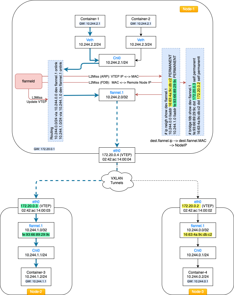
Now, lets do a deep dive and see the traffic flow when Container-1 wants to communicate with Container-3 as per the below diagram.
The network config of container-1 is as below:
Container-1 network config :
ip: 10.244.2.2,GW: 10.244.2.1
root@conatiner-1:/# ip a
2: eth0@if4: <BROADCAST,MULTICAST,UP,LOWER_UP,M-DOWN> mtu 1450 qdisc noqueue
    link/ether 86:3d:02:cf:4b:26 brd ff:ff:ff:ff:ff:ff
    inet 10.244.2.2/24 brd 10.244.2.255 scope global eth0
       valid_lft forever preferred_lft forever
    inet6 fe80::843d:2ff:fecf:4b26/64 scope link
       valid_lft forever preferred_lft forever
Routing table
root@conatiner-1:/# crictl exec 22a206cb47ea7 route -n
Kernel IP routing table
Destination     Gateway         Genmask         Flags Metric Ref    Use Iface
0.0.0.0         10.244.2.1      0.0.0.0         UG    0      0        0 eth0
10.244.0.0      10.244.2.1      255.255.0.0     UG    0      0        0 eth0
10.244.2.0      0.0.0.0         255.255.255.0   U     0      0        0 eth0
From the routing table, we see that cni0: 10.244.2.1 has been set as the default gateway. For packets to reach the 10.244.0.0/16 or 10.244.2.0/24 networks they need to go via the eth0 interface of the container. So the packet exits this interface and reaches cni0 via vetha1152ab4.
Vethxxx configuration
The Container-1 is connected to the Cni0 linux bridge via a veth pair. From the container’s ip address output: eth0@if4, we see that eth0 on the container is connected to an interface at index 4 on the host node. Looking at the host node interfaces we see that:
root@flannelcluster-worker:/# ip -d link show vetha1152ab4
4: vetha1152ab4@if2: <BROADCAST,MULTICAST,UP,LOWER_UP> mtu 1450 qdisc noqueue master cni0 state UP mode DEFAULT group default
    link/ether 8a:b2:3b:60:db:ba brd ff:ff:ff:ff:ff:ff link-netns cni-ce3a6e75-2310-bbec-a727-a4b7c8c6b132 promiscuity 1  allmulti 1 minmtu 68 maxmtu 65535
    veth
    bridge_slave state forwarding priority 32 .........
The output tells us that this interface is a bridge_slave to master cni0.
Cni0 network configuration
Cni0 is a linux bridge and vetha1152ab4 is attached to it.
root@flannelcluster-worker:/# brctl show
bridge name     bridge id               STP enabled     interfaces
cni0            8000.c6ea36fdacfa       no              vetha1152ab4
Once the packet reaches cni0 it looks at the routing table to figure out the next hop, as the Container-3 is in a different subnet. The routing table entries on the host node are as below:
Routing table
root@flannelcluster-worker:/# route -n
Kernel IP routing table
Destination     Gateway         Genmask         Flags Metric Ref    Use Iface
0.0.0.0         172.20.0.1      0.0.0.0         UG    0      0        0 eth0
10.244.0.0      10.244.0.0      255.255.255.0   UG    0      0        0 flannel.1
10.244.1.0      10.244.1.0      255.255.255.0   UG    0      0        0 flannel.1
10.244.2.0      0.0.0.0         255.255.255.0   U     0      0        0 cni0
172.20.0.0      0.0.0.0         255.255.0.0     U     0      0        0 eth0
From the routing table we see that:
10.244.2.0network is directly reachable on the host via thecni0interface.10.244.1.0and10.244.0.0networks are reachable via theflannel.1interface.
As Container-3 with ip 10.244.1.2 is on 10.244.1.0 network, after route look up the packet will be sent to the flannel.1 interface.
root@flannelcluster-worker:/# ip route get 10.244.1.2
10.244.1.2 via 10.244.1.0 dev flannel.1 src 10.244.2.0 uid 0
    cache
flannel.1 vxlan device
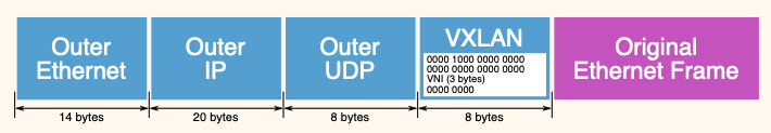
Once the packet reaches the vxlan device flannel.1 a few decisions are made. flannel.1 is a vxlan device that encapsulates the original ethernet frame inside a UDP packet and sends it over the vxlan tunnel to the destination VTEP.
Flanneld programs 3 things when ever a remote host is discovered either on startup or when they are added:
Step 1. Create routing table entry for the remote subnet. It goes via the vxlan device but also specifies a next hop (of the remote flannel host).
10.244.0.0      10.244.0.0      255.255.255.0   UG    0      0        0 flannel.1
10.244.1.0      10.244.1.0      255.255.255.0   UG    0      0        0 flannel.1
The second line here says, to reach the 10.244.1.0/24 network the nexthop is 10.244.1.0 which is the ip address of the flannel.1 device on that host node.
Step 2. Create a static ARP entry for the remote flannel host IP address (and the VTEP MAC)
root@flannelcluster-worker:/# ip neigh show dev flannel.1
10.244.0.0 lladdr 16:63:4a:9c:db:c2 PERMANENT
10.244.1.0 lladdr fe:93:66:89:29:9c PERMANENT
Step 3. Create an FDB entry with the VTEP MAC and the public IP of the remote flannel daemon.
root@flannelcluster-worker:/# bridge fdb show dev flannel.1
fe:93:66:89:29:9c dst 172.20.0.3 self permanent
16:63:4a:9c:db:c2 dst 172.20.0.2 self permanent
- Based on step 1, the nexthop is found to be
10.244.1.0. This is the flannel.1 ip address onnode-2. - The MAC address of the destination flannel.1 interface is figured out by using step 2. Here we see that
10.244.1.0has a mac address offe:93:66:89:29:9c. - Using step3, the destination node
node-2ip is figured out to befe:93:66:89:29:9c dst 172.20.0.3.
The below picture captures this flow:

Using this information, the packet gets vxlan encapsulated with the below parameters:
1. Outer MAC addresses:
    - Source MAC: `02:42:ac:14:00:04`             --> eth0 mac of Node1
    - Destination MAC: `02:42:ac:14:00:03`        --> eth0 mac of Node2
2. Outer IP addresses:
    - Source IP: `172.20.0.4`                     --> eth0 ip of Node1
    - Destination IP: `172.20.0.3`                --> eth0 ip of Node2
3. UDP details:
    - Source port: `50874`
    - Destination port: `8472`
4. VXLAN details:
    - VXLAN flags: `0x0800`
    - VXLAN Network ID (VNI): `1`
5. Inner L2 frame details:
    - Inner Source MAC: `fa:74:7b:d0:64:c6`       --> mac of flannel.1 on Node1
    - Inner Destination MAC: `fe:93:66:89:29:9c`  --> mac of flannel.1 on Node2
    - Inner Source IP: `10.244.2.8`               --> container-1 ip
    - Inner Destination IP: `10.244.1.8`          --> container-2 ip
    - Inner Protocol: ICMP (1)
    - ICMP Type: Echo (ping) request
A full VXLAN packet capture is as below:
Frame 1: 148 bytes on wire (1184 bits), 148 bytes captured (1184 bits) on interface eth0, id 0
Section number: 1
Interface id: 0 (eth0)
Interface name: eth0
Encapsulation type: Ethernet (1)
Arrival Time: Mar 24, 2024 10:53:28.299067865 UTC
[Time shift for this packet: 0.000000000 seconds]
Epoch Time: 1711277608.299067865 seconds
[Time delta from previous captured frame: 0.000000000 seconds]
[Time delta from previous displayed frame: 0.000000000 seconds]
[Time since reference or first frame: 0.000000000 seconds]
Frame Number: 1
Frame Length: 148 bytes (1184 bits)
Capture Length: 148 bytes (1184 bits)
[Frame is marked: False]
[Frame is ignored: False]
[Protocols in frame: eth:ethertype:ip:udp:vxlan:eth:ethertype:ip:icmp:data]
[Coloring Rule Name: ICMP]
[Coloring Rule String: icmp || icmpv6]
Ethernet II, Src: 02:42:ac:14:00:04 (02:42:ac:14:00:04), Dst: 02:42:ac:14:00:03 (02:42:ac:14:00:03)
Destination: 02:42:ac:14:00:03 (02:42:ac:14:00:03)
Address: 02:42:ac:14:00:03 (02:42:ac:14:00:03)
.... ..1. .... .... .... .... = LG bit: Locally administered address (this is NOT the factory default)
.... ...0 .... .... .... .... = IG bit: Individual address (unicast)
Source: 02:42:ac:14:00:04 (02:42:ac:14:00:04)
Address: 02:42:ac:14:00:04 (02:42:ac:14:00:04)
.... ..1. .... .... .... .... = LG bit: Locally administered address (this is NOT the factory default)
.... ...0 .... .... .... .... = IG bit: Individual address (unicast)
Type: IPv4 (0x0800)
Internet Protocol Version 4, Src: 172.20.0.4, Dst: 172.20.0.3
0100 .... = Version: 4
.... 0101 = Header Length: 20 bytes (5)
Differentiated Services Field: 0x00 (DSCP: CS0, ECN: Not-ECT)
0000 00.. = Differentiated Services Codepoint: Default (0)
.... ..00 = Explicit Congestion Notification: Not ECN-Capable Transport (0)
Total Length: 134
Identification: 0x64b4 (25780)
000. .... = Flags: 0x0
0... .... = Reserved bit: Not set
.0.. .... = Don't fragment: Not set
..0. .... = More fragments: Not set
...0 0000 0000 0000 = Fragment Offset: 0
Time to Live: 64
Protocol: UDP (17)
Header Checksum: 0xbd83 [validation disabled]
[Header checksum status: Unverified]
Source Address: 172.20.0.4
Destination Address: 172.20.0.3
User Datagram Protocol, Src Port: 50874, Dst Port: 8472
Source Port: 50874
Destination Port: 8472
Length: 114
Checksum: 0x58b3 [unverified]
[Checksum Status: Unverified]
[Stream index: 0]
[Timestamps]
[Time since first frame: 0.000000000 seconds]
[Time since previous frame: 0.000000000 seconds]
UDP payload (106 bytes)
Virtual eXtensible Local Area Network
Flags: 0x0800, VXLAN Network ID (VNI)
0... .... .... .... = GBP Extension: Not defined
.... 1... .... .... = VXLAN Network ID (VNI): True
.... .... .0.. .... = Don't Learn: False
.... .... .... 0... = Policy Applied: False
.000 .000 0.00 .000 = Reserved(R): 0x0000
Group Policy ID: 0
VXLAN Network Identifier (VNI): 1
Reserved: 0
Ethernet II, Src: fa:74:7b:d0:64:c6 (fa:74:7b:d0:64:c6), Dst: fe:93:66:89:29:9c (fe:93:66:89:29:9c)
Destination: fe:93:66:89:29:9c (fe:93:66:89:29:9c)
Address: fe:93:66:89:29:9c (fe:93:66:89:29:9c)
.... ..1. .... .... .... .... = LG bit: Locally administered address (this is NOT the factory default)
.... ...0 .... .... .... .... = IG bit: Individual address (unicast)
Source: fa:74:7b:d0:64:c6 (fa:74:7b:d0:64:c6)
Address: fa:74:7b:d0:64:c6 (fa:74:7b:d0:64:c6)
.... ..1. .... .... .... .... = LG bit: Locally administered address (this is NOT the factory default)
.... ...0 .... .... .... .... = IG bit: Individual address (unicast)
Type: IPv4 (0x0800)
Internet Protocol Version 4, Src: 10.244.2.8, Dst: 10.244.1.8
0100 .... = Version: 4
.... 0101 = Header Length: 20 bytes (5)
Differentiated Services Field: 0x00 (DSCP: CS0, ECN: Not-ECT)
0000 00.. = Differentiated Services Codepoint: Default (0)
.... ..00 = Explicit Congestion Notification: Not ECN-Capable Transport (0)
Total Length: 84
Identification: 0xa421 (42017)
010. .... = Flags: 0x2, Don't fragment
0... .... = Reserved bit: Not set
.1.. .... = Don't fragment: Set
..0. .... = More fragments: Not set
...0 0000 0000 0000 = Fragment Offset: 0
Time to Live: 63
Protocol: ICMP (1)
Header Checksum: 0x7e90 [validation disabled]
[Header checksum status: Unverified]
Source Address: 10.244.2.8
Destination Address: 10.244.1.8
Internet Control Message Protocol
Type: 8 (Echo (ping) request)
Code: 0
Checksum: 0x8086 [correct]
[Checksum Status: Good]
Identifier (BE): 59 (0x003b)
Identifier (LE): 15104 (0x3b00)
Sequence Number (BE): 1504 (0x05e0)
Sequence Number (LE): 57349 (0xe005)
Data (56 bytes)

0000  24 a9 4c b5 00 00 00 00 00 00 00 00 00 00 00 00   $.L.............
0010  00 00 00 00 00 00 00 00 00 00 00 00 00 00 00 00   ................
0020  00 00 00 00 00 00 00 00 00 00 00 00 00 00 00 00   ................
0030  00 00 00 00 00 00 00 00                           ........
Data: 24a94cb50000000000000000000000000000000000000000000000000000000000000000?
[Length: 56]
Once the packet reaches node-2 it gets decapsulated and the L2 frame is handed over to the flannel.1 interface which in turn will send it to the right destination container.