IP in IP (IPIP) tunnels using linux network namespaces

In this blog, lets explore how IPIP tunnels work using linux network namespaces.
Introduction
The IP-within-IP tunnel is akin to a VPN sans the encryption and multicast. It is generally used to join two internal IPv4 subnets over a pulic IPv4 internet. When a point-to-point tunnel is established between two machines, a virtual interface is created on both the sides and they are added to a new virtual network. This makes the local and remote network appear to be connected on the same network.
IPIP Packet structure
In IPIP tunneling, the original L3 packet from the source is encapsualated in an additional outer IP packet. The outer ip header has the source and destination ip addresses of the local and remote servers. The inner ip header has the source and destination ip addresses of the tunnel endpoints.
IPIP tunneling supported combinations
- IPv4 over IPv4
- IPv6 over IPv4
- IPv4 over IPv6
- IPv6 over IPv6
- MPLS over IPv4
- MPLS over IPv6
- Not encrypted
- Multicast not supported. Use GRE tunnels if you need multicast.
The outer IP header used for encapsulation adds an overhead of 20 bytes. Due to this reason, the MTU on the tunnel interface gets adjusted to 1500 - 20 = 1480 bytes.
6: tun0@NONE: <POINTOPOINT,NOARP,UP,LOWER_UP> mtu 1480 qdisc noqueue state UNKNOWN group default qlen 1000
    link/ipip 172.16.10.2 peer 152.16.10.2
    inet 192.168.50.1/30 scope global tun0
IPIP tunnels using network namespaces.
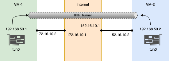
Lets tryout creating IPIP tunnels using linux network namespaces. The below pictures shows the topology:
Here, we have 3 network namespaces:
- host1 : ip 172.16.10.2 (veth0)
- internet (router) : ips 172.16.10.1 (veth1), 152.16.10.1 (veth2) (simulates the connectivity via internet routers)
- host2 : ip 152.16.10.2 (veth3)
The hosts are connected to the internet router via veth pairs. IP Forwarding is enabled on the internet router.
Two IPIP tunnel end points are created on host1 and host2:
- host1-tun0 : 192.168.50.1/30
- host2-tun0 : 192.168.50.2/30
Setup Script
Here a virtual point-to-point link is formed between host1:192.168.50.1 <—–> host2:192.168.50.2.
Now we can log in to one of our host namespaces and ping the other side of the tunnel.
# ping -c 3 192.168.50.2
PING 192.168.50.2 (192.168.50.2) 56(84) bytes of data.
64 bytes from 192.168.50.2: icmp_seq=1 ttl=64 time=0.094 ms
64 bytes from 192.168.50.2: icmp_seq=2 ttl=64 time=0.112 ms
64 bytes from 192.168.50.2: icmp_seq=3 ttl=64 time=0.124 ms

--- 192.168.50.2 ping statistics ---
3 packets transmitted, 3 received, 0% packet loss, time 2054ms
rtt min/avg/max/mdev = 0.094/0.110/0.124/0.012 ms
A tcpdump capture on the host shows the following packet structure for outgoing icmp request:
08:22:05.470882 IP (tos 0x0, ttl 255, id 14271, offset 0, flags [DF], proto IPIP (4), length 104)
    172.16.10.2 > 152.16.10.2: IP (tos 0x0, ttl 64, id 23058, offset 0, flags [DF], proto ICMP (1), length 84)
    192.168.50.1 > 192.168.50.2: ICMP echo request, id 34685, seq 1, length 64
08:22:05.470944 IP (tos 0x0, ttl 254, id 12437, offset 0, flags [DF], proto IPIP (4), length 104)
    152.16.10.2 > 172.16.10.2: IP (tos 0x0, ttl 64, id 15789, offset 0, flags [none], proto ICMP (1), length 84)
    192.168.50.2 > 192.168.50.1: ICMP echo reply, id 34685, seq 1, length 64
We can glean the following info from the icmp request of this output:
Outer IP Header
- IP : IP protocol is being used.
- ttl 255 : maximum ttl value. Indicates the packet is starting from the source.
- flags [DF] : Dont Fragment. Tells the router not to fragment this packet.
- proto IPIP (4) : protocol type is 4 for IPIP
- length 104 : total size of the packet.
- 172.16.10.2 > 152.16.10.2 : local server ip » remote server ip for packet traversal
Encapsulated IP Packet
Within the GRE tunnel, there’s another IP packet encapsulated:
- IP : IP protocol is being used.
- ttl 64 : ttl value
- proto ICMP (1) : ICMP protocol is being used.
- 192.168.50.1 > 192.168.50.2 : src and destination ips of the point-to-point tunnel link.

